
Printing Technical Drawings to Scale: Accurate CAD Guide
Sep 22, 2026
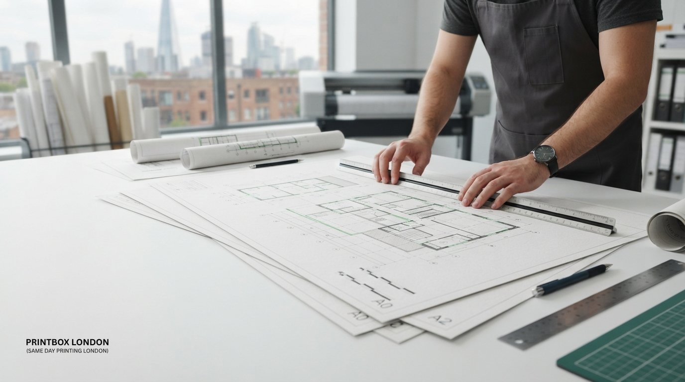
Default PDF print settings quietly shrink technical drawings by 2% to 6%, invalidating hours of precise drafting before a set of plans even reaches the building site. When you have properly configured your paper space viewports and checked your model units, printing technical drawings to scale should feel straightforward. Yet an unchecked "Fit to Printable Area" box or an overlooked plot offset easily distorts your layout, leading sub-contractors and site trades to miscalculate clearances, wall positions, and service runs from physical paper.
True scale accuracy ultimately depends on export settings and physical printer calibration rather than CAD geometry alone. In this guide, you'll learn how to export, size, and print architectural and engineering drawings to exact scale without costly site errors. We walk through proper ISO sheet selection from A0 to A3, vector PDF export rules, and essential scale bar verification checks that prevent planning invalidations and keep your project on schedule.
Key Takeaways
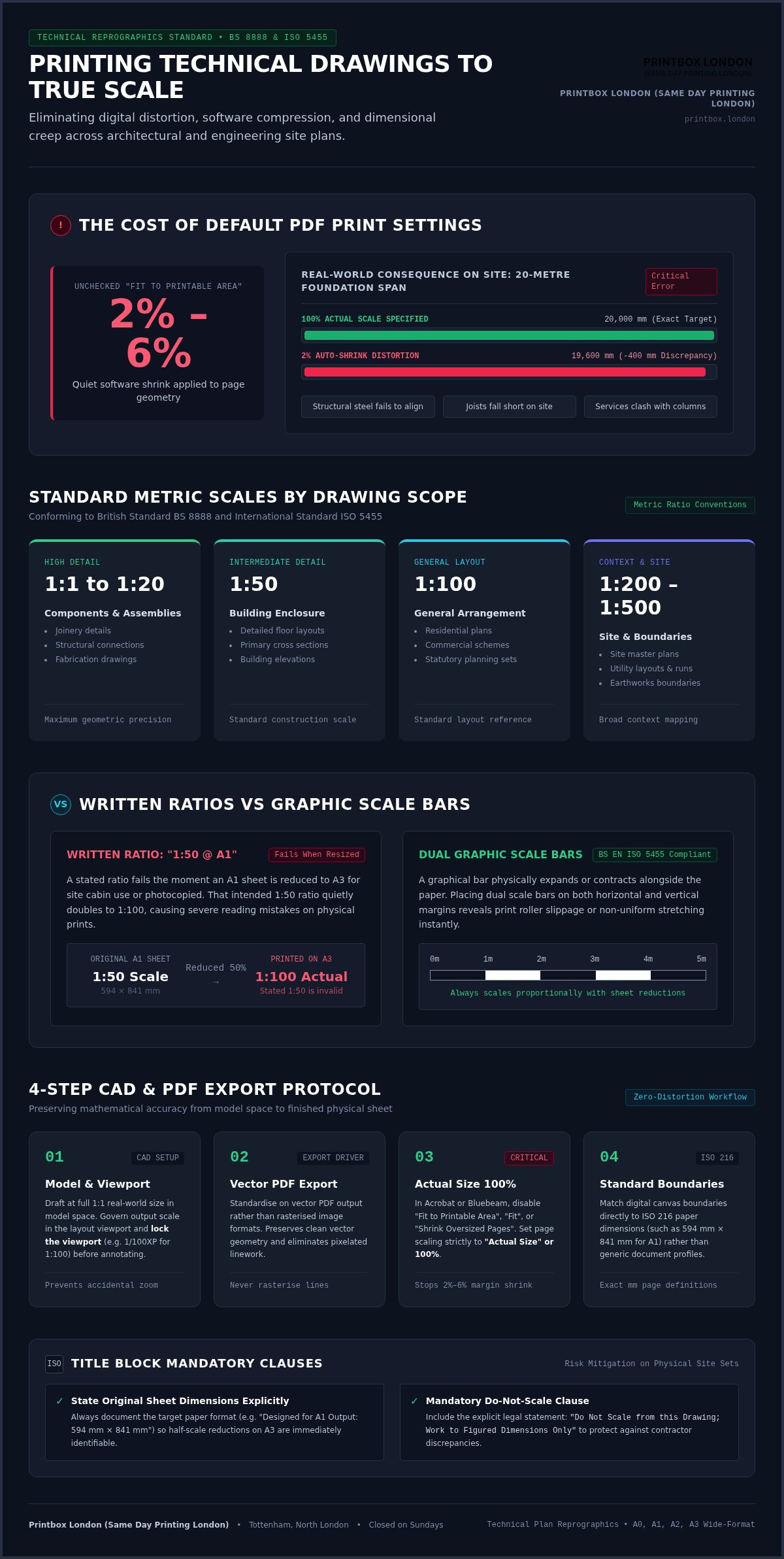
- Master standard metric ratios from 1:1 joinery details to 1:500 site layouts to maintain drawing compliance under BS 8888 and ISO 5455 standards.
- Eliminate distortion when printing technical drawings to scale by locking CAD paper space viewports and setting PDF drivers strictly to actual size at 100%.
- Pair project scopes correctly with standard ISO 216 sheet sizes from A0 to A3 to prevent line clutter and maintain proportional half-size reductions.
- Protect site builds against environmental paper shift by integrating graphic scale bars alongside physical scale rule calibration checks.
- Streamline technical submissions across London with wide-format reprographic workflows that prevent layer dropouts and margin clipping on site-ready sets.
Understanding Scale in Technical Drawings: Core Ratios and Precision
Technical drawing scale represents the exact mathematical ratio between a distance measured on paper and the actual dimensions of a physical structure. Unlike illustrative concept sketches that merely convey visual intent, legal construction working drawings demand absolute mathematical rigour. When you send files for architectural plan production, adhering to standard metric conventions established under BS 8888 and ISO 5455 prevents costly misinterpretations on site.
Different project stages require specific ratios to balance detail with context:
- 1:1 to 1:20: Component assemblies, joinery details, and structural connections.
- 1:50: Detailed floor layouts, primary sections, and building elevations.
- 1:100: General arrangement plans for residential and commercial structures.
- 1:200 to 1:500: Site plans, utility layouts, and earthworks boundaries.
Mastering these mathematical relationships is essential when printing technical drawings to scale, because even minor geometric shifts invalidate statutory planning checks or tender packages. In commercial fit-outs and specialised shopfitting where fixture detailing and spatial flow are paramount, you can visit hildebrands GmbH to see how expert retail design bridges the gap between technical planning and physical execution.
Ratio Scales Versus Graphical Scale Bars
A written ratio like "1:50 @ A1" fails the moment a document is resized, reduced to A3 for site cabins, or photocopied. If an A1 sheet is printed at half-size on A3, that stated 1:50 ratio becomes 1:100. Incorporating graphic scale ratios in technical drawings provides visual proof of geometric accuracy. A graphical bar physically expands or contracts alongside the drawing media. For complete compliance with BS EN ISO 5455, place dual scale bars along both the horizontal and vertical margins. This reveals non-uniform paper stretching or print roller slippage instantly.
The Financial Risk of Dimensional Creep on Site
A subtle 2% software shrink or print driver distortion might look negligible on a desk. Across a 20-metre foundation span, that error creates a 400 mm discrepancy on site. Structural steel will fail to align, prefabricated joists will fall short, and services will clash with structural columns.
Site trades routinely measure physical prints when checking rough openings. If they scale off an unverified sheet, project delays and legal liabilities follow. Protect your practice by pairing your title block with explicit instructions: state both the original design paper size and a clear "Do Not Scale from this Drawing; Work to Figured Dimensions Only" clause. When precise scaling is non-negotiable for estimators or site managers, printing technical drawings to scale through verified, uncompressed workflows remains your best defence against contractual disputes.
How to Export CAD and PDF Drawings at True 100% Scale
Achieving true dimensional accuracy on physical paper requires strict digital setup before you ever hit export. Whether working in AutoCAD, Revit, or Vectorworks, your drawing geometry must remain uncompressed from CAD paper space to the finished sheet. Drafting is carried out at full 1:1 real-world size in model space, but the output scale is strictly governed by your layout viewport. Locking this viewport ensures your scale factor (such as 1/100XP for 1:100) stays fixed while you annotate.
Always export your final drawings as vector PDFs rather than rasterised image formats. Standardising on high-resolution vector output preserves clean vector geometry, prevents pixelated linework, and ensures sharp detail when printing technical drawings to scale.
Disabling Auto-Fit and Margin Shrinking Settings
Default viewer options cause the vast majority of on-site measurement errors. Selecting "Fit to Printable Area", "Fit", or "Shrink Oversized Pages" in software like Adobe Acrobat or Bluebeam Revu forces the file within standard mechanical printer borders. This single selection reduces your sheet dimensions by 2% to 6%, turning an intended 1:100 layout into an unusable 1:104 ratio. Always set page scaling explicitly to "Actual Size" or "100% Scale". If you need assistance checking your export setup before a major submission, you can contact our team for file guidance.
Configuring Virtual Plotters and Exact Page Boundaries
Match your digital canvas directly to standard physical paper dimensions rather than generic document profiles. Follow these parameters for repeatable accuracy:
- Select standard sheet profiles: Use predefined ISO boundaries conforming to standard ISO 216 paper size specifications (such as 594 mm × 841 mm for A1) via drivers like DWG to PDF.pc3.
- Zero out printer margins: Pick "ISO full bleed" paper options to eliminate non-printable margins that clip title blocks.
- Lock layout scale: Set the paper space plot ratio strictly to 1:1 (1 mm = 1 drawing unit).
- Save verified profiles: Store proven plot setups within your project template to prevent accidental resets across drafting teams.
Embedding Vector Linework and Managing TrueType Fonts
Technical drawings rely on line weight hierarchy to separate cut sections from background hatching. Check your PDF driver properties to embed all TrueType fonts, which stops unexpected font substitutions from spilling over text boundaries. Finally, assign a monochrome colour-dependent plot style (CTB) so hairline linework retains distinct, legible thicknesses down to 0.13 mm without dropouts.
Matching Technical Scales to Standard ISO Paper Sizes
ISO 216 standardisation relies on a consistent 1:√2 aspect ratio, meaning each size halves cleanly into the next: A0 (841 mm × 1189 mm), A1 (594 mm × 841 mm), A2 (420 mm × 594 mm), and A3 (297 mm × 420 mm). When printing technical drawings to scale, matching your real-world scope to the right paper format is critical. Reducing an A1 drawing down to desktop A3 cuts the linear scale by exactly 50%. An intended 1:50 drawing turns into 1:100, which compresses line spacing, blurs dense hatch patterns, and renders uncalibrated site measurements completely inaccurate.
Use this reference matrix to pair technical drawing types with standard metric scales and ISO dimensions:
- 1:1 to 1:10 (A3 to A2): Detailed component fabrication, bespoke joinery, and structural steel connections.
- 1:20 to 1:50 (A1): General building sections, interior room layouts, reflected ceiling plans, and drainage elevations.
- 1:100 (A1 or A0): Whole-building floor plans and core structural framing layouts.
- 1:200 to 1:500 (A0 or Custom Rolls): Comprehensive site masterplans, block plans, and urban context mapping.
Standard Construction Scales and Associated Sheet Requirements
Selecting your sheet format early preserves drafting clarity. Detailed 1:1 assemblies fit comfortably on A3 or A2 sheets without wasting paper, whereas multi-storey general arrangements at 1:100 require the surface area of A1 or A0. For long infrastructure schemes like highway corridors or railway spurs, standard sheets fail to capture the scope. These projects rely on custom continuous roll lengths, keeping linear alignments intact without artificial sheet breaks. When preparing supporting planning packages for new highway or development access layouts, developers can also explore Transport Statements to ensure their technical traffic submissions meet council validation standards.
Choosing Between A0, A1, and A2 for Site Usability
Sheet selection involves practical on-site ergonomics as well as geometry. While A0 sheets offer ample space for expansive masterplans, managing a one-metre-wide drawing on windy scaffolding or inside a busy site van is notoriously difficult. For most UK principal contractors, A1 represents the operational sweet spot. It provides enough surface area to present clear 1:50 or 1:100 details alongside title blocks and revision tables, while remaining easy to fold and inspect on a workbench. For help evaluating which format best fits your current drawing register, explore our guide on A0 vs A1 architectural plans before sending your files to production.
Verifying Scale Accuracy and Media Stability on the Job
Physical quality assurance is just as critical as software configuration. Once your sheets leave the plotter, relying blindly on stated proportions can still lead to site errors if physical verification gets skipped. Wide-format print engines feed paper using mechanical friction rollers, which can occasionally slip or stretch the sheet unevenly. Establishing a strict quality check routine ensures your prints maintain true geometry from the print room table to the construction cabin.
Performing Physical Calibration and Dimension Checks
Never send unverified sets out to trades. Take two minutes to perform three essential checks with a calibrated steel rule or high-grade oval architectural scale rule:
- Gridline verification: Place your scale rule against a major figured structural gridline (such as a 5-metre bay spacing) to confirm it reads true.
- Scale bar alignment: Measure the printed graphic scale bar directly against your physical rule along both the horizontal and vertical sheet edges.
- Corner diagonal cross-check: Measure from opposite sheet corners across the layout frame. Unequal diagonal lengths reveal paper feed skew or trapezoidal distortion caused by uneven plotter pinch rollers.
Carrying out these checks confirms that printing technical drawings to scale succeeded without physical drift along either axis.
Paper Weight, Environmental Humidity, and Lamination
Standard 90 gsm uncoated wood-pulp bond paper remains the industry choice for daily working sets due to its sharp line contrast and easy folding. However, cellulose fibres are naturally hygroscopic. When unsealed paper moves from a dry office into damp UK site conditions, it absorbs airborne moisture. This hygroexpansion causes linear dimensional changes between 0.1% and 0.4%. On an A0 sheet spanning 1189 mm, a 0.3% moisture expansion shifts physical linework by roughly 3.5 mm.
For master site plans, groundwork drawings, or sheets exposed to outdoor weather, protective lamination or durable synthetic media preserves dimensional stability. Encapsulation seals the fibres against atmospheric moisture, preventing uneven swelling while protecting your critical linework from site grime and water damage.
Professional Plan Printing in London: Fast Turnaround for Technical Sets
Precision CAD drafting requires dedicated reprographic hardware to translate digital vectors into dependable physical site documents. Everyday office printers struggle with large-format files, often dropping intricate hatch patterns, truncating perimeter title blocks, or downsampling vector geometry into blurred lines. Professional raster image processors (RIPs) interpret raw CAD vector paths directly. This guarantees razor-sharp linework across complex architectural layouts, electrical schematics, and mechanical assemblies.
Working with a dedicated specialist simplifies printing technical drawings to scale. File pre-flight checks catch unscaled viewports, unflattened layers, and non-standard page bounds before jobs hit the media roll, saving both production time and site remediation costs.
Submitting Print-Ready Technical Drawing Packages
Preparing clean vector PDFs speeds up production and protects your project timeline. Ensure all external references (Xrefs) are bound into the base file before exporting so missing blocks do not create white space errors on paper. Check these items before submission:
- Flatten vector layers: Merge complex layer stacks to ensure transparent fills or revision clouds process without dropping underlying CAD linework.
- Specify output colour: Clarify whether you need crisp monochrome line printing or full-colour markups for site services coordination.
- Check sheet orientation: Set the export canvas to match the true aspect ratio of your layout to avoid orientation rotation during RIP processing.
For a detailed breakdown of formatting conventions across structural and civil disciplines, read our dedicated guide to engineering drawing printing in London.
Same-Day Plan Production and Collection in North London
Deadlines on London construction projects rarely leave margin for multi-day shipping delays. Printbox London (Same Day Printing London) produces wide-format technical plans directly from its South Tottenham production shop, serving architects, structural engineers, and site contractors across Greater London. When planning validation deadlines loom or urgent site sets are needed for contractor coordination meetings, same-day printing is available depending on quantity, stock, and specification.
Clients can collect their printed plan rolls directly in-store from 52 West Green Road, Tottenham, N15, or arrange rapid courier delivery direct to project sites across Central, North, East, South, and West London. To get started, send over your print-ready vector PDF files with your required ISO sheet sizes and quantities, and contact Printbox London (Same Day Printing London) to confirm availability and turnaround for your urgent drawing run.
Ensure Complete Site Accuracy with True-Scale Prints
Protecting your project from costly foundation misalignments and contractor disputes starts at the export window. By locking layout viewports, disabling automated margin fit presets, and verifying graphic scale bars against physical rules, printing technical drawings to scale becomes a repeatable science rather than a gamble on site.
When deadlines demand dependable plan sets without software dropouts, Printbox London (Same Day Printing London) provides high-resolution large-format plan printing across standard A0, A1, A2, and bespoke dimensions. Same-day turnaround is available depending on order quantity, specifications, and workshop capacity. Pick up your plan rolls directly from our shop in South Tottenham near Seven Sisters, or arrange rapid courier delivery across Greater London.
Submit your vector files today and get site-ready, dimensionally true prints into your team's hands without delay.
Frequently Asked Questions
Why did my drawing print slightly smaller than the specified scale?
Your PDF viewer or printer driver likely applied an automated reduction preset such as "Fit to Printable Area" or "Shrink Oversized Pages". These options force drawing boundaries inside mechanical printer margins, reducing page dimensions by 2% to 6%. To prevent this distortion when printing technical drawings to scale, always change your print dialogue scaling option to "Actual Size" or "100% Scale", and verify that your CAD plot setup uses borderless sheet definitions.
Can I print an A1 drawing onto an A3 sheet and still use a scale rule?
Yes, but you must adjust your scale rule accordingly. Because ISO 216 paper sizes scale proportionally by a factor of 1:√2, downscaling an A1 plan to an A3 sheet cuts linear dimensions by exactly 50%. A drawing originally drafted at 1:50 on A1 becomes 1:100 on A3, while a 1:100 layout becomes 1:200. Always check the printed graphic scale bar first to ensure the printer didn't add margin distortion.
What is the best file format for printing technical drawings to scale?
A vector PDF exported directly from your CAD or BIM software is the industry standard. Vector PDFs preserve exact geometric coordinates, maintain distinct line weight hierarchies, and prevent the pixelation common with raster image formats like JPEG or TIFF. Ensure all TrueType fonts are embedded, external references are bound, and the output canvas matches the target ISO paper boundary without added margins before sending it to the print shop.
Should I use a graphical scale bar or a written ratio on my plans?
You should include both, but the graphic scale bar is far more reliable. A written ratio like "1:100 @ A1" becomes invalid if someone prints the drawing on A3 or photocopies it. A visual scale bar resizes proportionally alongside the drawing geometry, offering immediate visual calibration. UK planning authorities also require explicit graphic scale bars alongside written ratios to prevent drawing invalidations during initial statutory validation checks.
How does paper humidity affect the dimensional accuracy of printed plans?
Standard wood-pulp bond paper naturally absorbs moisture from humid air, leading to physical hygroexpansion. When plans move between heated offices and damp construction sites across London, the paper fibres swell. This environmental shift can alter physical sheet lengths by 0.1% to 0.4%. On an A0 sheet, that causes a measurable shift of 2 to 4 mm, which is why structural engineers rely on figured dimensions rather than scaling off paper alone.
Can Printbox London (Same Day Printing London) print large-format drawings on the same day?
Yes, same-day printing is available for large-format CAD and architectural plans depending on the order quantity, file readiness, and workshop capacity. Orders are produced at our physical shop located at 52 West Green Road, South Tottenham, N15. You can collect your rolled plan sets in-store or arrange courier delivery throughout London. Contact Printbox London (Same Day Printing London) with your vector files to confirm the fastest turnaround for your deadline.
What paper weight should I choose for construction site drawings?
Uncoated 90 gsm CAD bond paper is the ideal standard for everyday construction drawings and site working sets. It provides crisp monochrome line contrast, folds cleanly into standard drawing wallets, and resists bleed-through from coloured highlighter markups. For exterior groundworks or long-term site cabin display boards where moisture and tears are common risks, consider encapsulated lamination to ensure your printed plans stay durable and legible throughout the build.
Article by
Printbox London Team
The Printbox London (Same Day Printing London) team provides practical printing guidance based on real customer requirements and day-to-day print production. We serve customers across Greater London from our Tottenham print shop, with same-day printing available for many products depending on quantity, specification, artwork and production capacity.